When deciding what type of gauges to install in my 86 C10, I decided on Dakota Digital (DD). One because of the ease of installation (I didn't have to hack up my existing dash bezel) and the looks. I think it will be cool to have digital gauges.
If you are interested, buy them form Chris on this forum - best prices around and the money supports this forum

.
Before I get into the nitty gritty, you will have to decide what you want the system to do (other than the obvious). For example, the basic Dakota Digital does not come with gear shift sending unit. So if you want the dash system to show what gear you are in, then this module is required. Also the adjustable dimming cannot be done through the stock headlight switch. Another special dimming switch (pentometer) can be ordered through Chris or DD. The system will dim but only to a set limit with the basis dash system (it is not adjustable like the stock headlight rheostat). You can look up all the available options at:
http://www.dakotadigital.com/index.cfm/page/ptype=product/product_id=158/category_id=66/home_id=59/mode=prod/prd158.htmThe DD gear selection system comes with a neutral safety switch with back-up light function built in (if you need these functions). Otherwise, you can bypass them and use the stock set-up. I went ahead and used them because my stock neutral safety/back-up switch was in poor condition.
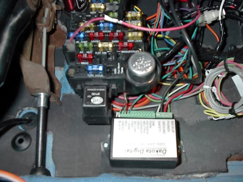
The first thing to decide on is where you mount the modules that control the system. The basic dash system has one module and if you get the optional gear shift sending unit - it has a module. I installed the gear shift sending module under the fuse block:
Then I found a spot to intall the basic dash control module above my ashtray bracket. Since I donot have A/C this makes a perfect spot. Keep in mind that the instructions say to route the sensor wires away from high current wires - so this spot accomplishes this requirement:
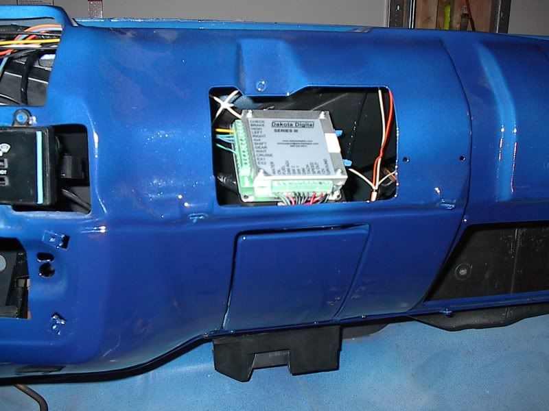
I modified the bracket that came with my Painless wiring harness to hold this module. It would be easy to make any type of bracket needed or just attach it to the firewall.
Now, for the gear shift selector module to work, I had to connect the gear selector switch to the transmission. The gear selector switch has a multitude of ways to do this for variuos transmissions - just follow the detailed instructions.
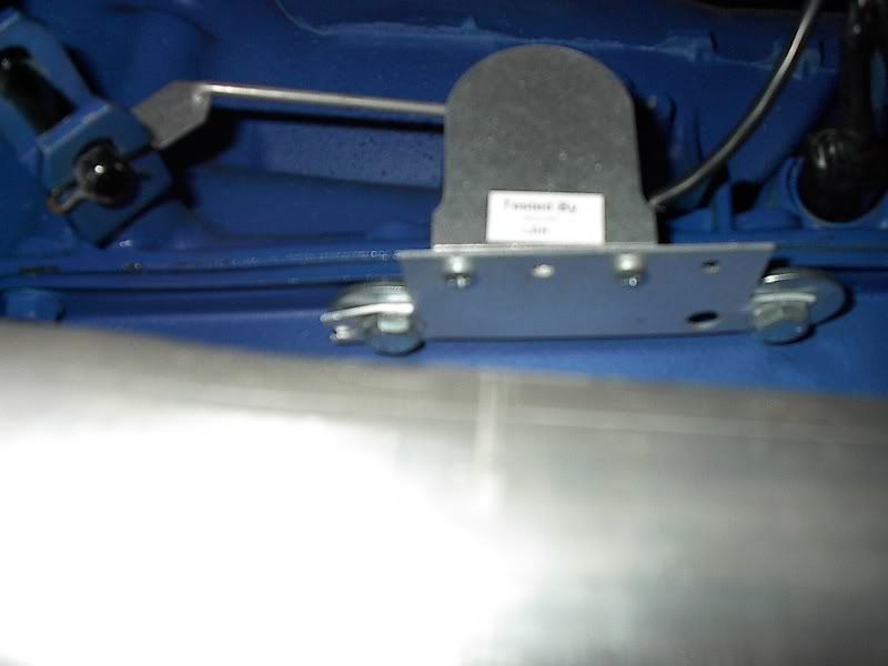
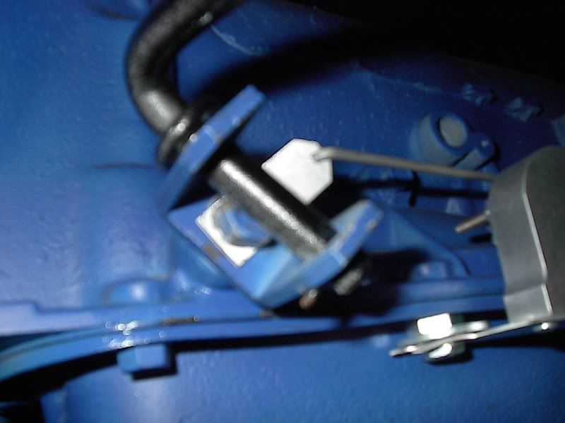
The gear selector switch has a single bundle of wire that gets routed to the gear selector module in the cab. Hook up the three wires from the switch to the module. Power is applied through a circuit that is hot in both key on and start. I tapped into my coil circuit. That is the only wire that is hot in both run and start on my Painless harness. I fussed it at 5 amps (after talking to a DD technician). From here, I wired in the nuetral safety switch relay. This was real easy - just follow the instructions. One purple wire that goes from the ignition switch to one leg of the relay, then to the starter solonoid. For the control side of the relay, one wire goes to the safety terminal on the gear selection module and the other is a hot wire in both key on and run (remember this is just a signal wire for the relay - no high amperage required). Again this was connected to the coil circuit. Now to wire in the back-up lights - I connected the hot wire TO the back-up lights to the back-up terminal of the gear selection module (this circuit is protected to 15 amps - according to the instructions). Thats it for the gear selection module except a ground wire to chasis ground and a single signal wire from this module to the DD dash module.
THIS IS NOT AS COMPLICATED AS IT SOUNDS

Now for the DD dash module. This part is pretty straight forward. Just follow the instructions. Mount the module in a location that will keep the sensor wires away from any high amperage wires. I powered the DD module with my main dash harness hot wire from the fuse panel - this also supplies the signal to the voltage gauge (real easy). Then attach a ground (at least 16 gauge wire) to chasis ground. Now go back underneath the vehicle and disconnect the speedometer cable and completely remove it. In its place attach the speed sensor - it screws into the hole that the speeometer cable came out of. Now twist the wires around each other (signal and ground wires) as you route the wires to the the DD module. I didn't twist mine (missed it in the instructions) so we will see if it work. If not, I'll have to go back and redo this portion of my install). This has something to do with noise cancellation. Now connect the red wire to "speed" terminal on the DD module and the black wire goes to chasis ground. I connected it to the "ground" terminal on the DD module.
Now it's just a matter of installing the various sensor wires to the DD Dash - water temp, oil pressure, tach, 4X4, turn signal, high beam, check engine, etc... Just follow the instructions for the various sensors you have or components. If you do not have a particular sensor/component, just leave the terminal open on the module. The dimmer wire needs to come off the park light circuit on the headlight switch, because, like I mentioned before, the headlight dimmer cannot control the DD. The DD dash module just needs a signal that the lights came on (therefore dim). The stock dash dimming circuit still need to go to the other dimming function of the radio and heater/AC control. One other important note - you have to use the sensors that come with the system for the system to work. For example the DD dash system comes with its own tempand oil pressure sensor that you HAVE to use - no other sensor will work. Just install these sensors in place of the stock sensor and you will be set. The DD system even comes with some adaptors to help with the install. I had to buy some additional 1/4 inch adapters to move the oil pressure sensor away from my distributor.
Now you need to attach two selector (normally open push button switches) to the dash bezel - I havn't done this yet. These switches connect to the DD module and go to ground. These switches switch between the various functions that the DD dash is capable of.
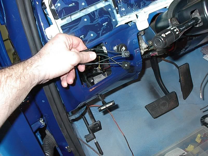
Now for the dash install. What is nice with this system is that there is no bezel work required - everything is ready to install. Just route the flat data cable to the DD module and plug it in - it only plugs in one way and route the flat ribbon cable away from anything that can cut it.
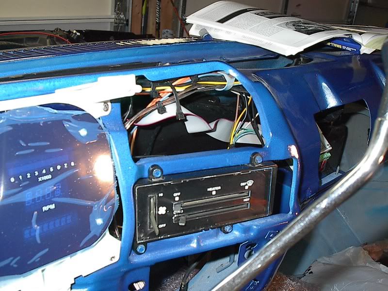
Now install the dash:
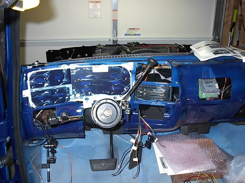
That is it except the minor work to your dash cover that fits over the DD dash. You need two small holes for the two switches and the DD system comes with matching plastic covers to glue to the dash cover to cover up the turn signal light holes and the gear selection slot (if you go with the DD gear selection system). Well that is it. I hope I didn't miss anything. For those of you that have done this install, if you see something wrong or have done something different please and your input.