I know there are a few people running the Spicer External "Hub Loc" on their Dana 44 equipped trucks still and thought this may be somewhat informative. Included are a few tips that I've used to keep the hubs in working order.
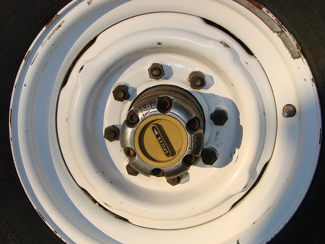
For the 1973 through 1977 Chevrolet/GMC K20/K2500 trucks without full time four wheel drive, the Spicer lockout was the factory original equipment lockout hub. Beginning in 1977, GM 3/4 ton trucks used a front axle that utilized the smaller K10/K1500 style "internal" locking hubs. In the 1973 - 1977 form, the Spicer hub is characterized by the yellow plastic knob with "Spicer" on the face and the large outer chrome ring.
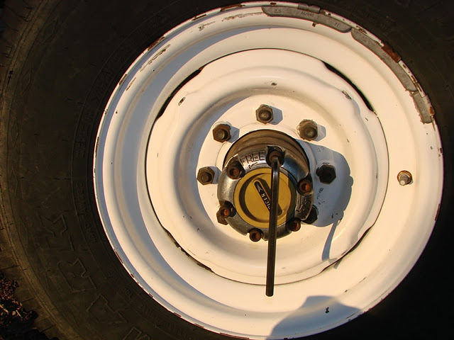
Here is a view of the 1973 - 1977 Spicer External Locking "Hub Loc" on a 1973 GMC K2500.
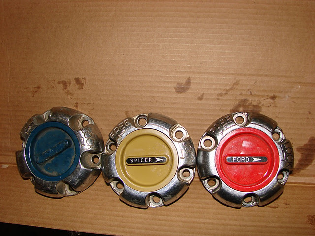
During the same time frame, Ford utilized the same hub from Spicer. The FoMoCo units had a red knob with "Ford" in the center instead of "Spicer". The same Spicer external locking hub was used on '72 back Chevrolet and GMC trucks with a blue knob and '72 back Fords with the red knob. Many of the basic parts to the hub extend back to the early 1960's for GM and Ford trucks. While there may be other applications, the vast majority of the units came on 3/4 ton GM and Ford 4x4 trucks with a Dana 44 front axle.
Views of the early 70's, 73-77 GM and early 70's -77 Ford Spicer "Hub Loc" External locking hub dials.
The Dana Corporation has posted the Service Manual for the Dana 44 "Hub Loc" External Locking Hub:
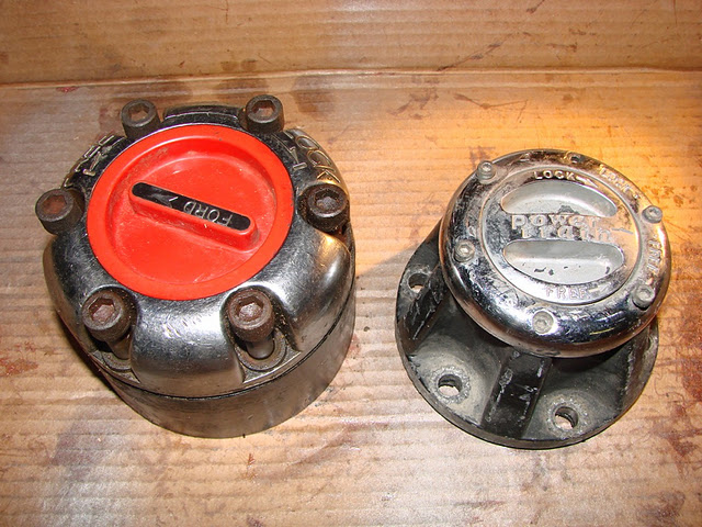
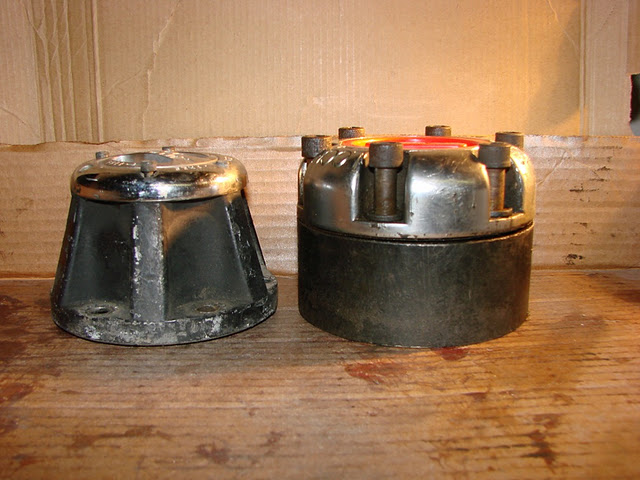
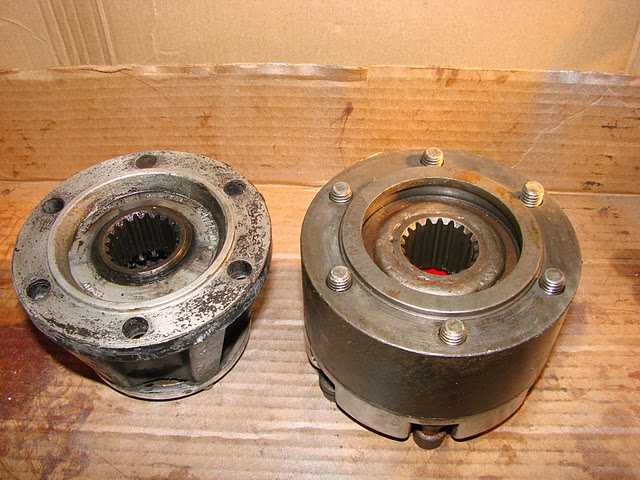
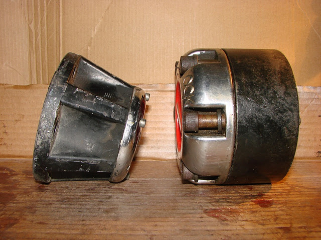
http://www2.dana.com/pdf/5305.pdfHere is a photo comparison of the Spicer hub and a replacement Spicer Powertrain hub. The Powertrain hub is the same basic design as a Warn or Milemarker external locking hub replacement. I took these photos after I had installed the GM set, so I grabbed a Ford set to show the physical differences. The weight comparison of the Spicer Hub Loc versus the Spicer Powertrain is significant. I didn't weigh them out, but just the inner clutch gears on the Hub Loc would weigh more than the complete replacement style hub.
Beginning the refurbishment process, all 6 allen head bolts are removed. with a 5/16" allen wrench.
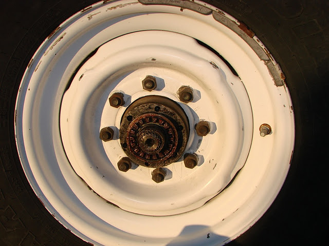
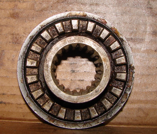
Once the outer portion of the hub is removed (actuating knob and gear hub housing), you're left with the inner clutch gear and it's bushing. Sometimes the bushing is tight into the body of the gear hub housing (big black part of the hub), then you have to remove the chrome ring and clutch gear from the hub housing and remove the snap ring (next photo) from the stub shaft.
Snap ring pliers remove the snap ring from the stub shaft.
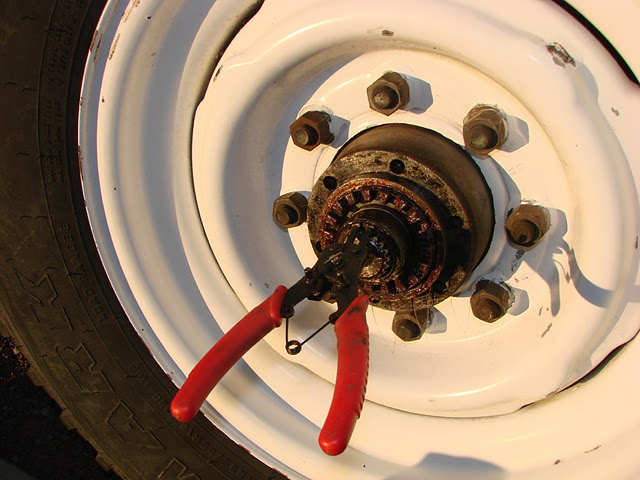
Then you slide the axle shaft inner clutch gear off the stub shaft.
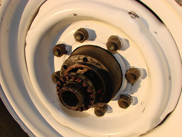
Then you have the bushing for the axle shaft inner clutch gear left to remove.
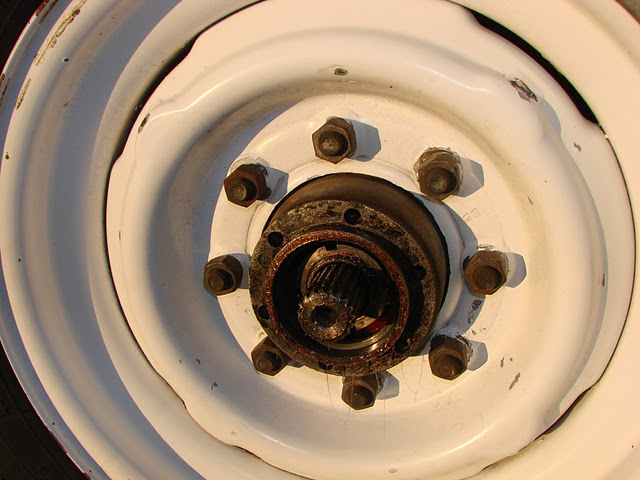
All the Spicer Hub Loc parts removed.
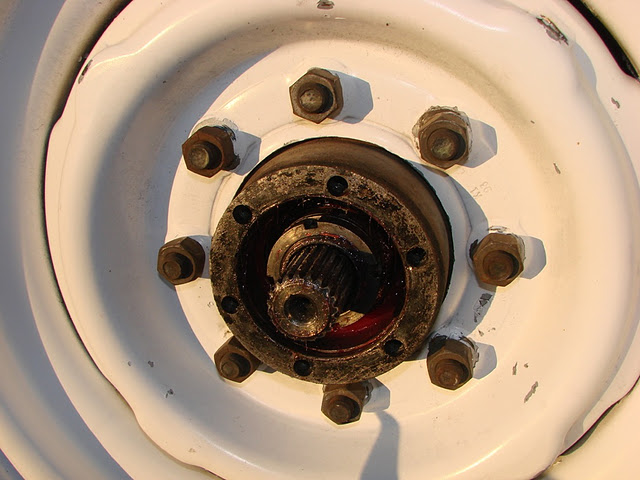
Next onto the tear down of the Spicer Hub Loc.
Here we have the actuating knob (plastic dial) retainer ring and outer clutch gear assembled onto the actuating cam. A pressure spring forces the outer clutch gear to the end of the actuating cam. If you push the clutch gear back against the spring you'll the clutch gear snap ring. While holding the clutch gear back against the spring, I used a flathead screwdriver to pull the snap ring out of the groove on the actuating cam. This will release the clutch gear and spring from the outer actuating assembly.
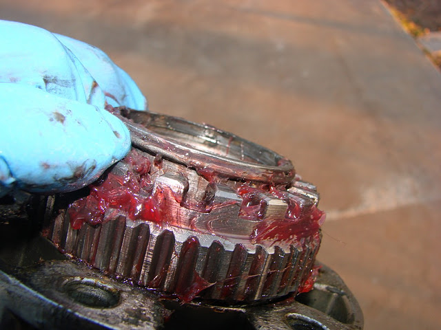
An alternate view of the clutch gear pressed back and the snap ring on the actuating cam
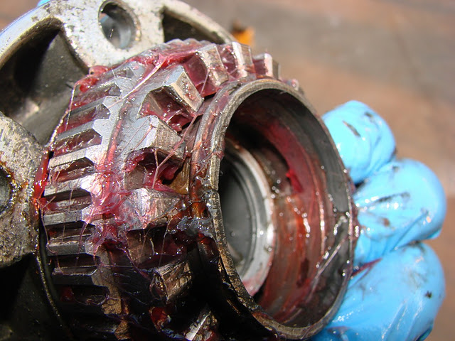
Once the outer clutch gear, pressure spring and clutch gear snap ring are removed the actuating cam is revealed in all it's actuating cam glory.
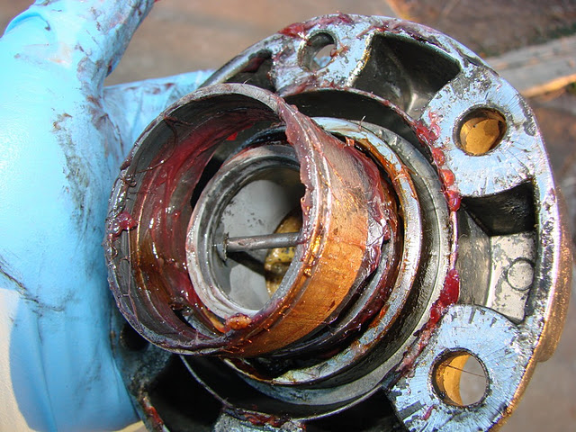
The actuating cam is held to the actuating knob (plastic dial) by the actuating cam pin. The pin rides within the slots on the actuating cam. This is a needle nose plier affair. It may be snug but shouldn't be overly difficult to remove with a pair of needle nose pliers.
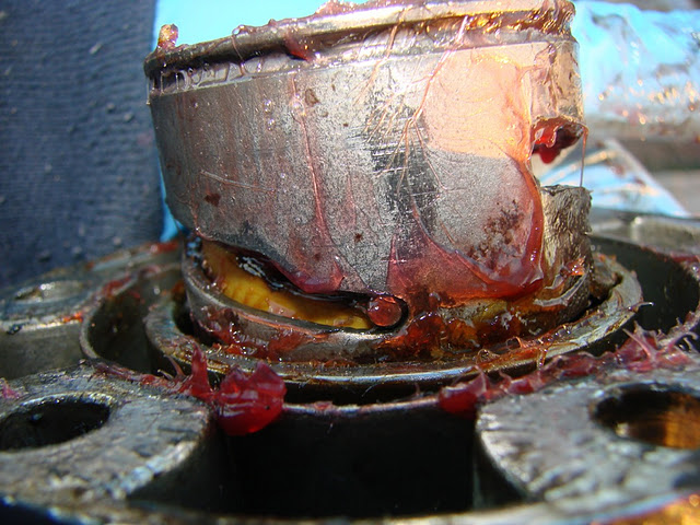
Next comes about the hardest part of the tear down. Within the actuating knob housing (chrome part) is the actuating knob (plastic dial) retainer snap ring. The snap ring rides within a groove on the actuating knob and can be a PITA to remove. The snap ring can barely be seen along the outer portion of the plastic actuating knob within the chrome actuating knob housing.
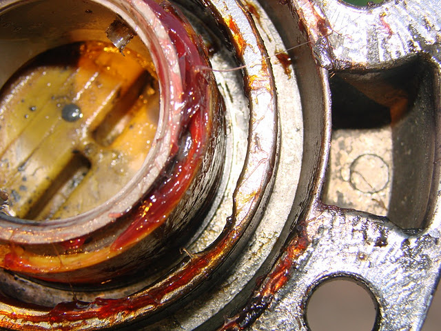
Once the actuating knob retaining snap ring is removed, the major disassembly is complete. I used kerosene to soak the parts to remove grease and grim.
As many have noted, the weak link on the Spicer hubs is the plastic actuating knob. Primarily due to ignorance, I encountered "problems" many years ago with a pair of NOS Spicer knobs and wound up breaking them. Not wanting to repeat my mistakes, I repaired my broken knobs and tried to make it into a lesson.
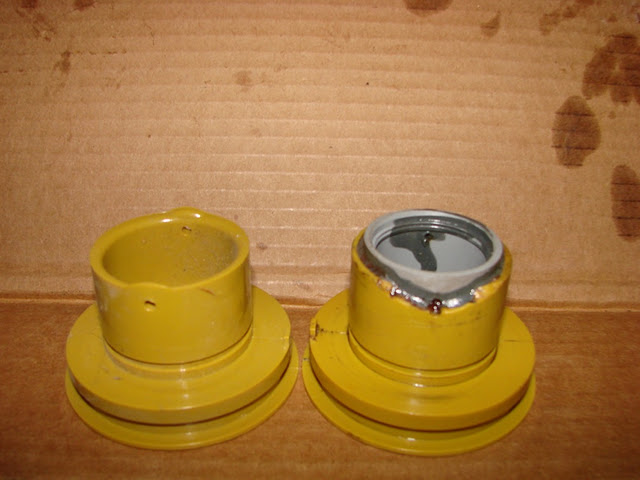
Here is a comparison of the Spicer actuating cam knobs (plastic dial). The knob on the right is a NOS Spicer knob., the knob on the left has been repaired. Also note, as part of the disassembly the actuating knob o-ring has been removed. To repair the Spicer knob, I used a piece of electrical PVC conduit. I had the conduit turned down on a lathe to fit snug into the knob, checked the fit and then glued it into the knob using all purpose PVC solvent. It's nice to have a retired machinist as a neighbor. After the glue dried, I drilled holes through the conduit to fit the actuating cam pin. This repair has lasted nearly a decade now.
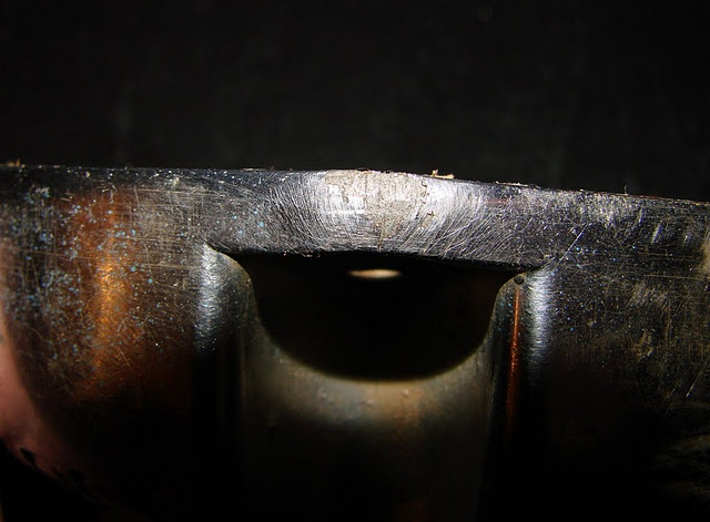
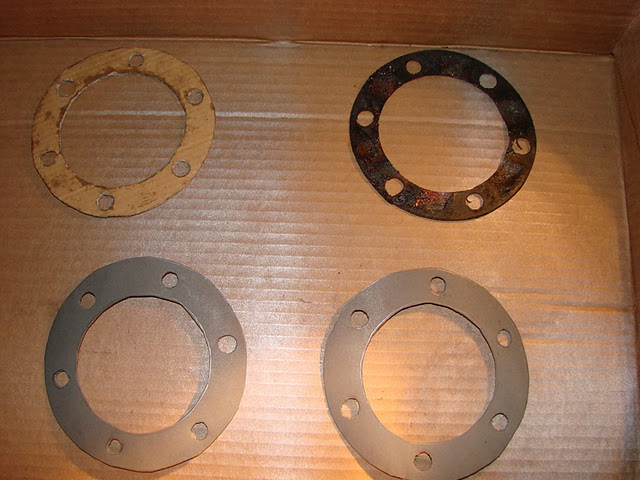
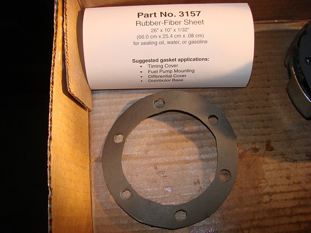
Another problem with hubs that have been discontinued for 20 some years is that gaskets and o-rings are not always readily available. I have some NOS gaskets, but didn't want to use them on this rebuild. The stock inner metal gaskets were usable, the outer paper gaskets were in poor shape. I purchased gasket material, Fel Pro #3157, which is slightly thicker than the stock gasket. As the chrome actuator housings were slightly deformed around the bolt holes (most that I've seen are this way), the extra thickness of the gasket will make up for the slight difference around the bolt holes. I made a template from the original gasket and then used the template to cut new gaskets. The original gasket and template will be kept with my spare hub parts.
View of distortion that I've found common to Spicer external Hub Locs.
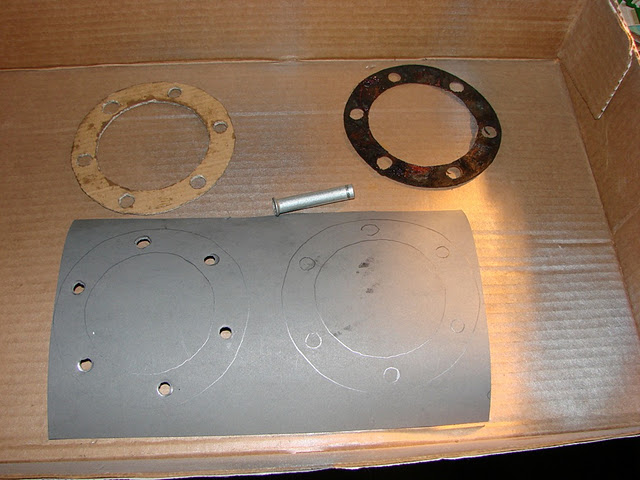
View of the original gasket (top right), template (top left) and progress on the replacement outer hub retainer gasket. I used a piece of 3/8 steel line that had been cut with a pipe cutter to get the majority of the material punched out from the bolt hole locations. The hole the steel line left was slightly undersized, so I had to do some trimming to make the hole the correct diameter for the bolts.
Progress on the replacement outer hub gaskets. Basically, they are to shape but need some trimming and cleanup.
Another view of new outer hub gasket and Fel Pro package sheet. The gasket is still in the rough in state and will be trimmed slightly more before assembly.
The O-ring that seals the plastic actuating knob to the chrome actuating knob housing is not a normal O-ring. It seems that it is a specific Spicer part. While a normal O-ring of sufficient diameter can be used (if necessary), it really is best if the original Spicer type O-ring is used. Here is a comparison of an O-ring that will work (left side of photo) to the original Spicer O-ring (right side of photo). The Spicer O-ring is stepped and has a groove on the top side (outer side). The inside of the Spicer O-ring fits snugly against the plastic actuating knob forming a better seal than the round profile O-ring would.
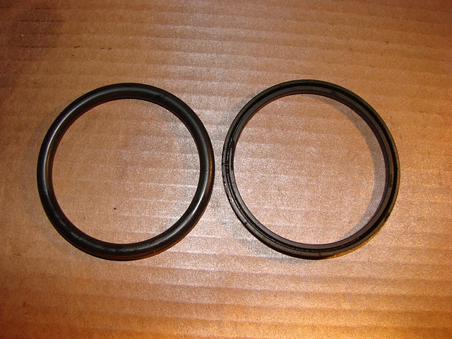
and another comparison view of the two O-rings.
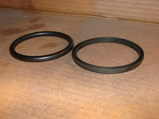
Here is a profile view of the original Spicer O-ring. The flat on top of the o-ring in the photo would face to the outside as installed. The profile shows how the sealing surface is stepped.
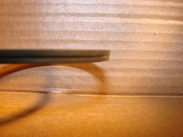
Another place to look at when rebuilding a Spicer Hub Loc is the inner clutch gear bushing. It is the part that the inner clutch gear (which slides over the stub shaft) rides within, as well as indexes the lockout hub assembly to the wheel hub. It is made of a soft metal and will wear quickly if not lubricated. This photo attempts to show the amount of wear that can occur on a well used inner clutch bushing. There is about 1/8" of wear from the top of the inner clutch gear to the inner clutch bushing. The inner clutch gear is much harder so it can and will destroy the bushing if there is no lubrication. A bushing like this may be repairable so I'll keep it just in case. Replacement bushings, like everything else on the Spicer hub are still out there (they just can be pricey when found).
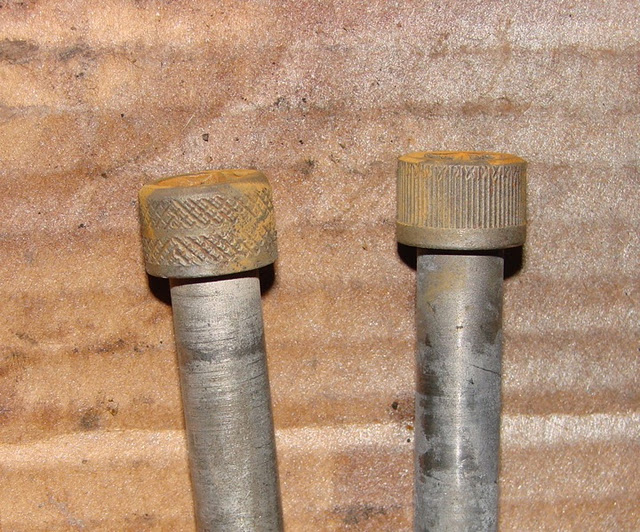
For the concours correct restoration crowd, it seems that there were at least two allen bolt types used on the Spicer hubs. There was a straight splined allen head that I've seen mostly on GM and then the cross hatched allen bolt head that I've seen on Fords. The cross hatch head also occurs on the bolts carrying the correct part number for Ford trucks. I haven't verified the GM bolts as of yet. So GM may have had straight splines and Ford may have had cross hatched. I cannot absolutely corroborate that.
Now for Part II: Reassembly of the Spicer Hub Loc.
So now that everything is cleaned up and you're thinking it would have taken much less time to slap on a new pair of aftermarket hubs, here comes the assembly.
The first part of the assembly is mating the O-ring to the actuating knob assembly. The groove on the O-ring faces to the outside of the hub as finally assembled. The Spicer manual specifies an O-ring lubricant, I used Ace brand Silicone that said it was specifically for lubricating O-rings and rubber parts. Not wanting to skimp on the lubricating the parts that face some of the harshest environment, I was generous with the silicone.
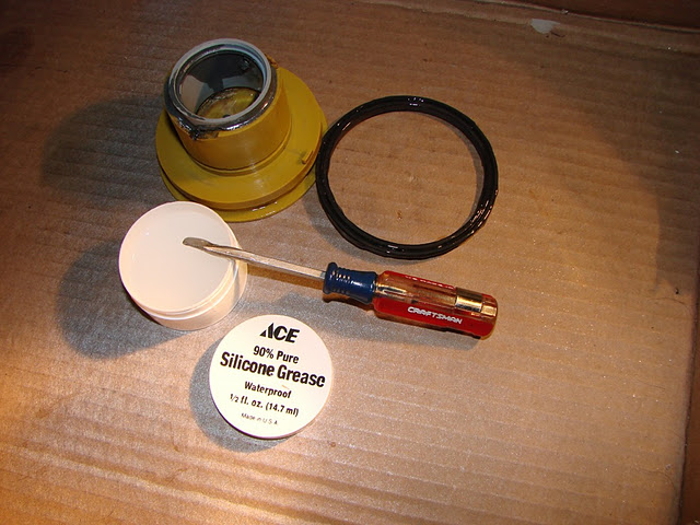
This photo shows the Spicer O-ring installed with the silicone lubricant. Note the groove in the plastic actuating knob, this is where the actuating knob retainer will snap into.
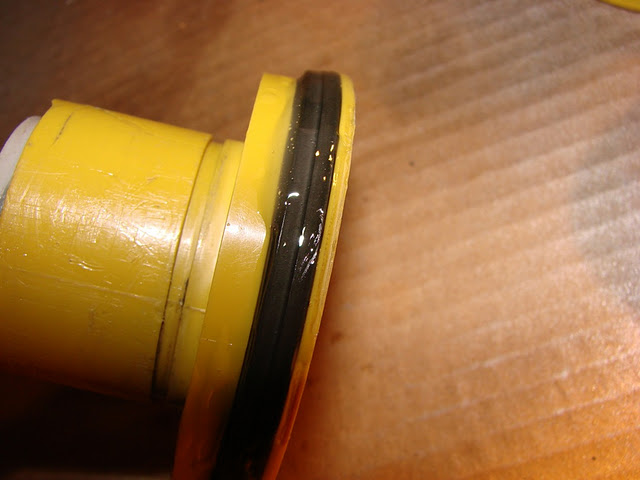
It'll be pretty evident once everything is together correctly, but the plastic actuating knob has a tab that indexes into a groove within the chrome actuating housing retainer.
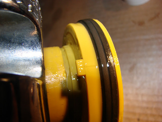
View of the plastic actuating knob installed into chrome actuating knob retainer (housing).
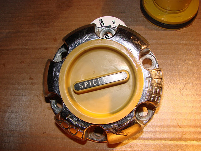
Next comes the snap ring that holds the plastic actuating knob to the chrome actuating knob retainer.
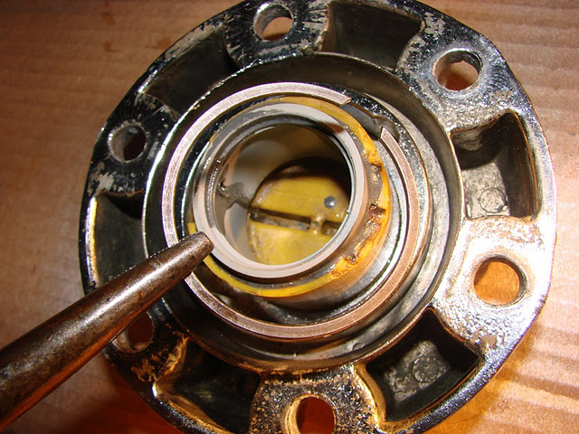
Place the snap ring onto the plastic actuating knob and slide it home into the snap ring groove. Make sure you don't have any last minute things to do to the plastic knob, because this snap ring can be a bit difficult to get back off.
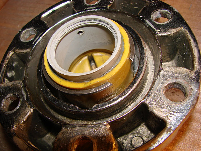
Once the actuating knob snap ring is in place, apply grease to the actuating cam. Primarily this will be the portion that the pin rides in and the outer side.
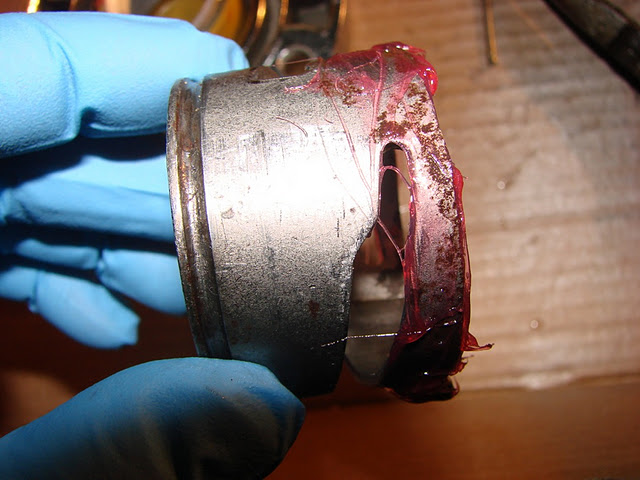
Line up the slot in the actuating cam with the hole in the plastic actuating knob and install the actuating cam pin.
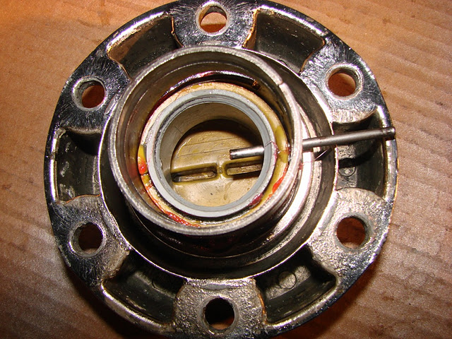
View of actuating cam installed onto plastic actuating knob.
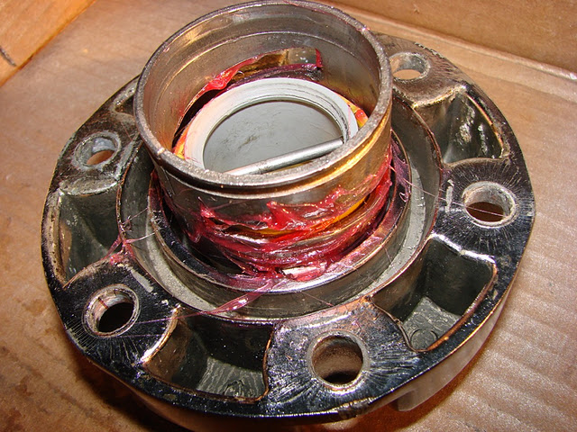
Install outer clutch gear pressure spring over actuating cam. I went ahead and greased the spring side where it met the chrome actuating knob retainer.
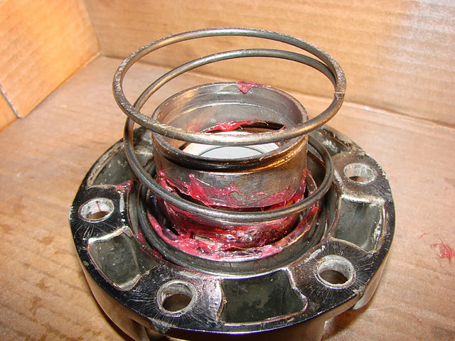
Grease inner surfaces of outer clutch gear and place onto outer clutch gear pressure spring.

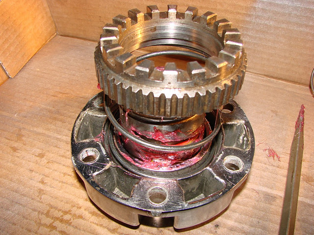
Outer portion of locking hub assembled, minus housing.
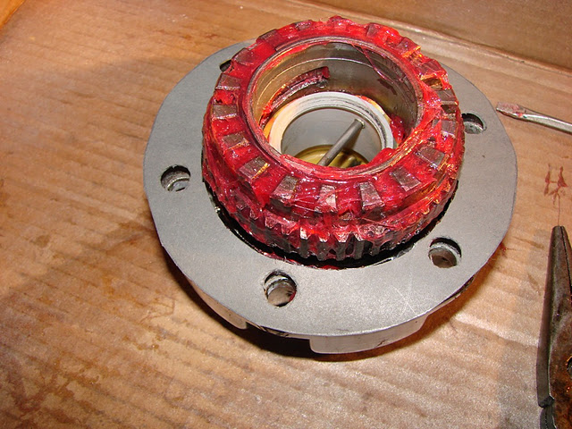
Gear hub housing with inner clutch gear bushing installed and the metal gasket. I used Permatex #2 non-hardening gasket sealer on the metal gasket.
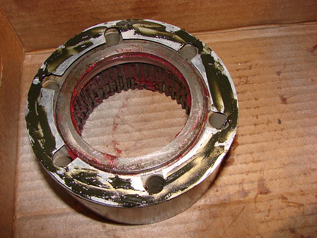
Installing gear hub housing, inner clutch gear bushing and metal gasket to wheel hub. A 3/8" coarse thread bolt with the head cut-off can aid in alignment. I didn't use an alignment bolt on this job.
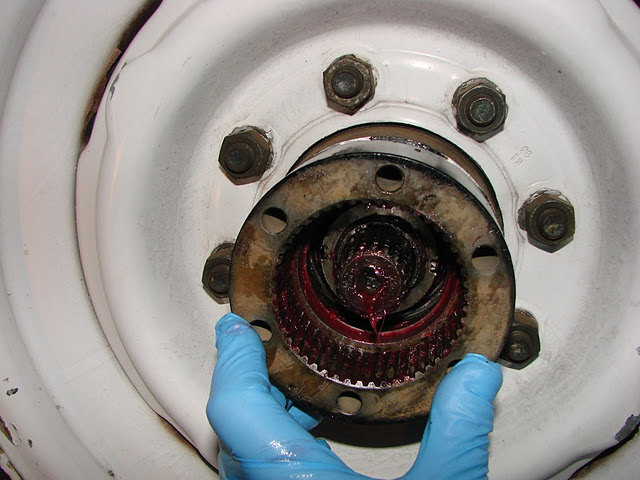
Install the inner clutch gear into the gear hub housing and reinstall the snap ring.
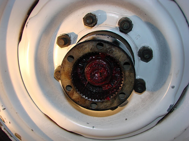
Finally, install the outer actuating retainer/outer actuating gear assembly, torque down the bolts and clean up the residual grease from the hub assembly.
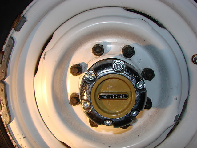
One thing to keep in mind about the Spicer Hub Loc hubs is that you should never have to force them. With proper maintenance they take minimal effort to engage and disengage. If they require force, then there is a problem. Most likely the problem is lack of lubrication on the gear housing spines, outer clutch gear splines, actuating cam or the plastic actuating knob. In general the common denominator is a lack of lubrication. Pliers may help to engage the hub, but they won't solve the underlying problem.