Quote:
Ya....OK... Try my little site glass test on 1 of your perfect engines and see what happens.
Whats your problem? I stated a fact and you take it personal? A correctly functioning Crank case ventialtion system should never cause an oil consumption problem, the problem lies somewhere else. A good engine builder asks himself if hes fixing the symptom or the problem?
Heres some helpful information on PCV and CCV systems.

PCV Systems
During the last stages of combustion in an engines cylinders,
some unburned fuel and products of combustion
leak past the piston rings and move into the crankcase.
This leakage is called blowby. Blowby must be removed
from the engine before it condenses in the crankcase and
reacts with the oil to form sludge. Sludge, if allowed to
circulate with engine oil, corrodes and accelerates wear
of pistons, piston rings, valves, bearings, and other internal
working parts of the engine.
Blowby gases must also be removed from the crankcase
to prevent premature oil leaks. Because these gases
enter the crankcase by the pressure formed during combustion,
they pressurize the crankcase. The gases exert
pressure on the oil pan gasket and crankshaft seals. If the
pressure is not relieved, oil is eventually forced out of
these seals.
Because the air/fuel mixture in an engine never completely
burns, blowby also carries some unburned fuel
into the crankcase. If it is not removed, the unburned fuel
dilutes the engines oil. When oil is diluted, it does not lubricate
the engine properly, which causes excessive wear.
Operation Combustion gases that enter the crankcase
are removed by a positive crankcase ventilation (PCV)
system, which uses engine vacuum to draw fresh air
through the crankcase. This fresh air enters through the
air filter or through a separate PCV breather filter located
on the inside of the air filter housing.
When the engine is running, intake manifold vacuum
is supplied to the PCV valve. This vacuum moves air
through the clean air hose into the rocker arm cover. From
this location, air flows through cylinder head openings into
the crankcase, where it mixes with blowby gases.
The mixture of blowby gases and air flows up through
cylinder head openings to the PCV valve. Intake manifold
vacuum moves the blowby gas mixture through the
PCV valve into the intake manifold (Figure 319).
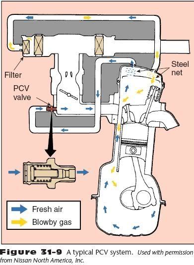
The blowby gases mix with the intake charge and enter the
combustion chambers, where they are burned.
The PCV system prevents the emission of blowby
gases from the engine crankcase to the atmosphere and
scavenges the crankcase for vapors that could dilute the
oil and cause it to deteriorate or that could build undesirable
pressure in the crankcase. An inoperative PCV
system could shorten the life of the engine by allowing
harmful blowby gases to remain in the engine, causing
corrosion and accelerating wear.
PCV Valve The PCV valve (Figure 3110)
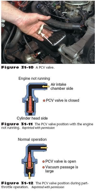
is usually mounted in a rubber grommet in one of the valve covers.
A hose is connected from the PCV valve to the intake
manifold. A clean air hose is connected from the air
cleaner to the opposite rocker arm cover. A filter is positioned
in the air cleaner end of the clean air hose. On some
systems, the PCV valve is mounted in a vent module, and
the clean air filter is located in this module.
A PCV valve contains a tapered valve. When the engine
is not running, a spring keeps the tapered valve
seated against the valve housing (Figure 3111).
During idle or deceleration, the high intake manifold vacuum
moves the tapered valve upward against the spring tension.
Under this condition, the blowby gases flow through
a small opening in the valve. Since the engine is not under
heavy load, the amount of blowby gas is minimal and the
small PCV valve opening is all that is needed to move the
blowby gases out of the crankcase.
Manifold vacuum drops off during part-throttle operation.
As the vacuum signal to the PCV valve decreases,
a spring moves the tapered valve downward to increase
the opening (Figure 3112). Since engine load is higher
at part-throttle operation than at idle, blowby gases are
increased. The larger opening allows all the blowby gases
to be drawn into the intake manifold. When the engine is operating under heavy load with a wide throttle opening, the decrease in intake manifold vacuum allows the spring to move the tapered valve further downward in the PCV valve
(Figure 3113),
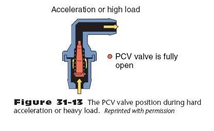
providing a larger opening through the valve. Since higher
engine load results in more blowby gases, the larger PCV
valve opening is necessary to allow these gases to flow
through the valve into the intake manifold.
When worn rings or scored cylinders allow excessive
blowby gases to enter the crankcase, the PCV valve opening
may not be large enough to allow these gases to flow
into the intake manifold. Under this condition, the
blowby gases create a pressure in the crankcase, and some
of these gases are forced through the clean air hose and
filter into the air cleaner. When this action occurs, there
is oil in the PCV filter and air cleaner. This same action
occurs if the PCV valve is restricted or plugged.
If the PCV valve sticks in the wide-open position, excessive
airflow through the valve causes rough idle operation.
If a backfire occurs in the intake manifold, the
tapered valve is seated in the PCV valve as if the engine
were not running. This action prevents the backfire from
entering the engine, where it could cause an explosion.
Fixed Orifice Tube PCV System Some engines are
equipped with a PCV system that does not use a PCV
valve. Instead, the blowby gases are routed into the intake
manifold through a fixed orifice tube.
The system works the same as if it had a valve,
except that the system is regulated only by the vacuum
on the orifice. The size of the orifice limits the amount of
blowby flow into the intake. The engines air/fuel system
is calibrated for this calibrated air leak. Since the action
of the PCV allows unmetered air into the intake, the
air/fuel system must be set for this amount of extra air.
PCV SYSTEM DIAGNOSIS
AND SERVICE
No adjustments can be made to the PCV system. Service
of the system involves a careful inspection, operation, and
replacement of faulty parts. Some engines use a fixed orifice
tube in place of a valve. These should be cleaned periodically
with a pipe cleaner soaked in carburetor cleaner.
Although there is no PCV valve, this type of system is diagnosed
in the same way as those systems with a valve.
When replacing a PCV valve, match the part number on
the valve with the vehicle makers specifications for the
proper valve. If the valve cannot be identified, refer to the
part number listed in the manufacturers service manual.
If the PCV valve is stuck in the open position, excessive
air flow through the valve causes a lean air/fuel ratio
and possible rough idle operation or engine stalling.
When the PCV valve or hose is restricted, excessive
crankcase pressure forces blowby gases through the clean
air hose and filter into the air cleaner. Worn rings or cylinders
cause excessive blowby gases and increased crankcase
pressure, which forces blowby gases through the
clean air hose and filter into the air cleaner. A restricted
PCV valve or hose may result in the accumulation of
moisture and sludge in the engine and engine oil.
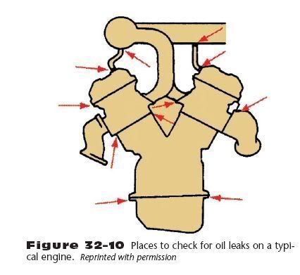
Leaks at engine gaskets, such as rocker arm cover or
crankcase gaskets, will result in oil leaks and the escape
of blowby gases into the atmosphere. However, the PCV
system also draws unfiltered air through these leaks into the engine.
This action could result in wear of engine components,
especially when the vehicle is operating in dusty
conditions. Check all the engine gaskets for signs of oil
leaks (Figure 3210).
Be sure the oil filler cap fits and
seals properly.
The first step of PCV servicing is a visual inspection.
The PCV valve can be located in several places. The most
common location is in a rubber grommet in the valve
cover. It can be installed in the middle of the hose connections,
as well as installed directly in the intake manifold.
Once the PCV valve is located, make sure all the PCV
system hoses are properly connected and that they have
no breaks or cracks. Remove the air cleaner and inspect
the air and crankcase filters. Crankcase blowby can clog
these with oil. Clean or replace such filters. Oil in the air
cleaner assembly indicates that the PCV valve or hoses
are plugged. Make sure you check these and replace the
valve and clean the hoses and air cleaner assembly. When
the PCV valve and hose are in satisfactory condition and
there is oil in the air cleaner assembly, perform a cylinder
compression test to check for worn cylinders and piston
rings.
Functional Checks of the PCV System
A rough-idling engine can signal a number of PCV problems,
such as a clogged valve or a plugged hose. But before
beginning the functional checks, double check the
PCV valve part number to make certain the correct valve
is installed. If the correct valve is being used, continue by
disconnecting the PCV valve from the valve cover, intake
manifold, or hose. Start the engine and let it run at idle.
If the PCV valve is not clogged, a hissing is heard as air
passes through the valve. Place a finger over the end of
the valve to check for vacuum (Figure 3211).
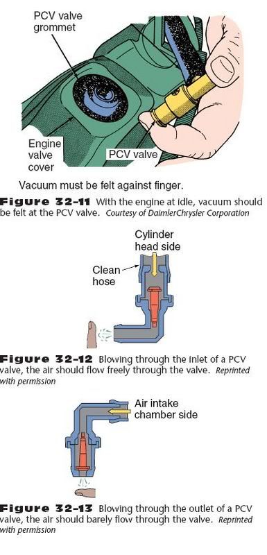
If there is little or no vacuum at the valve, check for a plugged or restricted hose. Replace any plugged or deteriorated hoses. Turn off the engine and remove the PCV valve. Shake the valve and listen for the rattle of the check needle inside the valve. If the valve does not rattle, replace it.
Some vehicle manufacturers recommend that the valve be checked by removing it from the valve cover and hose. Connect a hose to the inlet side of the PCV valve,
and blow air through the valve with your mouth while
holding your finger near the valve outlet (Figure 3212).
Air should pass freely through the valve. If air does not
pass freely through the valve, replace the valve. Move the
hose to the outlet side of the PCV valve and try to blow
back through the valve (Figure 3213). It should be difficult
to blow air through the PCV valve in this direction.
When air passes easily through the valve, replace the
valve.
Another simple check of the PCV valve can be made
by pinching the hose between the valve and the intake
manifold (Figure 3214) with the engine at idle.
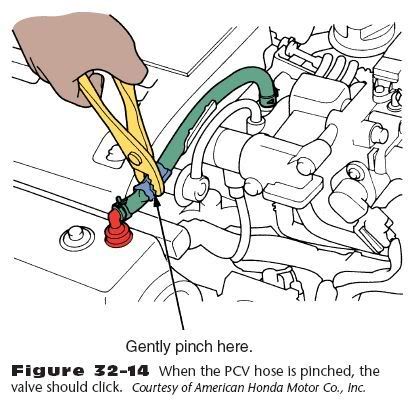
You should hear a clicking sound from the valve when the
hose is pinched and unpinched. If no clicking sound is
heard, check the PCV valve grommet for cracks or damage.
If the grommet is all right, replace the PCV valve.
Remember that proper operation of the PCV system
depends on a sealed engine. The crankcase is sealed by
the dipstick, valve cover, gaskets, and sealed filler cap. If
oil sludging or dilution is found and the PCV system is
functioning properly, check the engine for oil leaks and
correct them to ensure that the PCV system can function
as intended. Also, be aware of the fact that an excessively
worn engine may have more blowby than the PCV system
can handle. If there are symptoms that indicate the
PCV system is plugged (oil in air cleaner, saturated
crankcase filter, and so forth) but no restrictions are
found, check the wear of the engine.
Edited by: VileZambonie  at: 3/11/07 10:18 am

 1
1
