Well, I was able to find time to sit down and post another update on the ol' battleaxe. It seemed like the last post was approaching the length of a Shakepeare classic, hopefully this one wont eclipse the page count of War and Peace. I guess I should try to update this thread on a weekly basis so that when I do post it will be less to read every time. That whole pastor's sermon goes on and on until you lose your audience sort of thing......
So here it is.
I finally can call the frame complete (sort of):

I was able to construct the engine mounts in a way I believe they will work the best.


The engine will sit slightly low in the frame to start. I will most likely have to space the engine mount upward to get the engine in the factory position once the body is on. I did it this way because I feel it would be easier to space the mounts upward rather than to try to build new mounts that would drop the engine. These are the solid engine mounts that I had built for the sled puller configuration.
I also built the engine mounts to accomodate the return to factory rubber insulated frame mounts should I ever elect to do so.

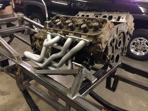

In these pictures are visible the framework I built to mount the clutch linkage:

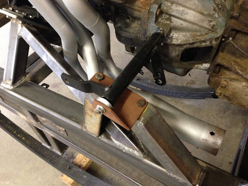

After I set the engine in the frame I measured, measured, and measured some more. I determined the engine needed to be moved forward one inch to avoid interfering with the cab's firewall. So, this is the modification to the transmission mount that was the result of moving the enigne:

My transmission mount was built with the intention of being able to raise or lower the rear of the transmission, or changing it all together to facilitate the install of a TH-400, or 4L80E at some point should I ever (doubtfully) decide to go that route.
I stated that I like to mock everything up mutiple times before the final build. I believe it was our good friend "illinoisk30" who said "measure twice, cut once" my philosophy is "I've cut it three times, and it is still too short". (hahaha!)
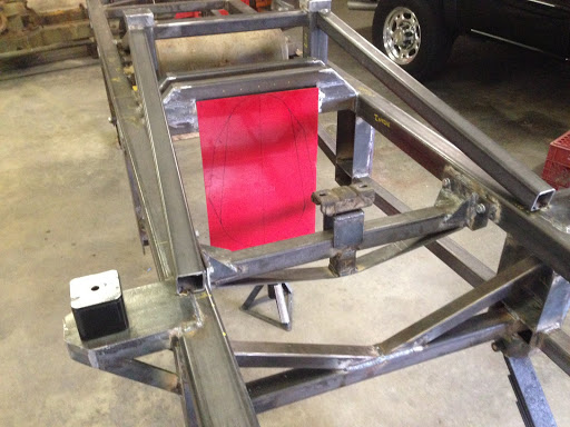
Seriously, I made a likeness of a puller transfer case that replicates one that I intend to use in order to check my first driveshaft angle. Looking good. So good that I didn't bother to concern myself with calculating the angles, which in retrospect I should have done for future reference.

In the next photograph the wood block approximates where the top of the axle will be in relation to the springs.

The awesome thing about the 2.5~5-ton Rockwell military axles is that their double reduction gearing moves the driveshaft connection point way up above the axleshaft centerline.
About 10":

I wanted to see how much I could get away with before I had any driveline binding issues. So, I dropped the driveshaft all the way down to see how much I could drop the transfer case before the angle became too severe.


I could probably drop the transfer case 4" and get away with it. However, I would want to avoid introducing any driveline harmonics unecessarily so I will look at keeping it in the 2"~3" drop range but only if it is required to lessen the angles on the driveshafts to the axles, and only if they are severe. The transfer case will be centered so as to use identical 1610 series 5-ton driveshafts front, and rear.
Here is the rub to dropping the transfer case- I would like to avoid dropping the transfer case if I do not have to. The transfer case input will be parallel with the horizontal axis of the frame. The engine and transmission are located with the GM designed 6° nose up from horizontal. To keep the driveshafts to the axles equal I cannot rotate the transfer case upward the way GM did with the rear axle to match the engine. In order to prevent introducing a vibration the effort is to keep the u-joints in similar phase. The high (or low) angles are not so much a problem as is keeping the u-joint angles similar so that one u-joint's phase change cancells out the opposite's phase change.

In the process of doing this build I have added tabs and other bracketry for mounting brake lines, vent lines, fuel lines, and so forth. I'll still need to add brackets to hold a fuel cell over the rear axle. The hydraulic steering will need brackets for the steering valve, hoses, reservoir, and a steering fluid cooler.
Bracket for the brake line to brake hose bulkhead fitting:

I'm reusing much of the brake plumbing that I purchased for the puller build.
A little bracket for the axle vent tubes:

I bought these cool looking coiled hoses to vent the axles:

I'm going to have to make some minor tweaks to my leaf springs. When I had these built I sort of figured that would be the case. I am somewhat still in the school of hard knocks as far as leaf spring design goes. Spring rate, deflection, etc.
I built my frame around a 60" eye center span leaf spring based on sizes, specifications, and components of exisiting Chevy truck springs. Knowing that the length would grow as I added weight I had the spring built to a 58.75" span. After adding the weight of the engine, and transmission to the bare frame I had already exceeded my target of 60". I built the mount for the shackle to sit 90° to the spring eyes with the full weight of the truck on it sitting on level ground.
This being a "compression shackle" design (truck's weight pushing down on the shackle) when the spring cycles the shackle in its normal arc past my 90° target it will effectively lower the spring rate of the spring. This gives a better overall ride, but allows the input forces to the spring to deflect the spring easier. By starting the shackle with an angle of less than 90° you raise the effective spring rate of the spring prior to its passing the center (90°) point. This can result in a choppy, or harsh ride if the spring isn't built with a soft rate in the begining.
Thinking of it this way, if the shackle is leaning inward toward the spring as the spring is pushed upward by road shock, the shackle will be swinging downward in its natural arc as the force of the bump is trying lift the spring. After the shackle passes the mid point, its arc will then allow it to travel in the natural direction of the input force. (The above ONLY applies to a compression shackle. -Think front of our 4x4 trucks. It it the exact opposite theory applied when the leaf spring is mounted with a tension shackle design. -This is what is found on the rear of our trucks)
As I said, I had exceeded my target eye span with just the weight of the engine, and transmission. To similate the cab, front end, hood, steering valve, engine accessories, bumper, frame addition, etc. I added (and intentionally overloaded) the front of the frame (you know, that mock up of things before final assembly

). This is the springs with 600# of added weight:
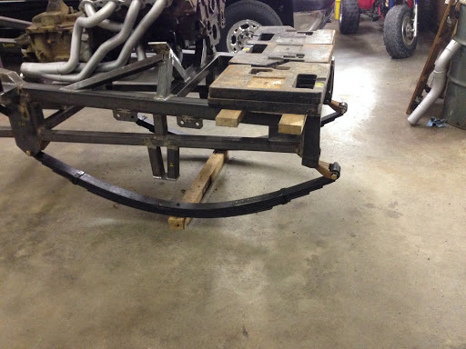
In this picture, ideally, I want an imaginary line drawn through the centers of the shackle bolts to be straight up and down:

After finding out that I would need to tweak the springs I once again called the guys up at StLouis Spring. Man, these guys are aces to deal with. As anyone may have noticed all through this thread I have intentionally left out names of products I have used. The reason for this is because nobody is paying my to use their camshaft, or shock absorbers. However, I feel mentioning StLouis Spring is warranted because these guys have been so helpful with answering stupid questions over the phone, and only seem eager to help me with my latest needs.
In fixing my springs I need to shorten the main leaf slightly. I am looking at a 57" eye center. If this can be accomplised by bending more arch into the spring then that will be super. The critical factor is that about all StL Spring can phyisically bend into a leaf spring is roughly 14~15" of arch measured from an imaginary line drawn through the eyes to the top of the main leaf. So, if the spring can't be drawn up to 57" naturally then the main leaf will need to be shortened ever so slightly. The guys at StL Spring have already expressed a desire to make the re-arch solution work before shortening the main leaf, so I am optimistic that the main leaf can stay as is. Also, I'll be increasing the static spring rate by about 33%. I am going to have them add two more leaves to the pack. Again, this build is about height, not an active 4x4 off road suspension.
Recently my oldest son, and I had a conversation as to why I placed my shackle toward the front on the front spring as opposed to the tradtional rear of the front spring. If you look at my design it is a "poor man's 4-link":

As mentioned earlier, the springs will want to travel in a natural direction away from the end that is anchored to the frame in the direction of the shackle. By mounting the springs inboard, and having them travel outwards the axle will migrate in the direction that the swing of the torque rods (some people call these traction bars) take as they cycle. The location, and height of the center mount on my frame is no accident. It serves two purposes. 1) To mount the transfer case. 2) By placing the mounted end of the torque bars at the point they appear in my drawing, the horizontal forward movement of the axle end of the torque bar as it swings through its arc will be a similar movement to the horizontal forward movement of the center of the leaf spring. (which would theorhetically be 1/2 of the shackle's movement)
"Back in the day", and maybe still today, even with the interwebs, some guys would mount their spring shackle on the rear of the front spring, and then would have to build into the traction bar a hydraulic cylinder with a dampening type of plumbing between the two chambers of the cylinder to allow for the rearward travel of the front axle as it cycled. This, to me, seems counter logical at the very best. Other than the slight dampening effect of the hydraulic cylinder, minus any air in the system, it is useless. With a setup like that your leaf springs are doing more than just holding up your truck. They have to counteract the power, and braking torque, and that was only made worse by the fact that almost every truck used/uses blocks between the spring, and axle for height. The block translated into leverage against the spring.......and the more a spring is worked the sooner it reaches its failure threshold. And yes, almost every major monster truck did this, and got away with it......even the potentate Bigfoot.
(Caveat emptor- or why you want your springs like our square bodies have them from the factory) One MAJOR advantage to having the shackle on the rear of the front spring is that you don't have the natural tendancy of the spring to wander. The extra pivot point lets the springs yaw laterally, something you dont get with the front of the front spring being anchored on the front of the truck. Ford solved this with their 99~04 Super Duty by adding a track bar to their leaf spring fronts........Just food for thought, and not really applicable to an 80's monster truck but just thought I would throw it in here.
A short time ago my son texted me with some excellent news. Earlier in this thread I mentioned working out a deal for a triple/double roll bar (pictured in the yellow truck). I had given up the idea of getting it because the deal became too much work. Well I think the good Lord loves classic Chevy monster trucks. With out fail every thing that I have wanted for this build, tires, axles, bed, tailgate, and other body parts, have eventually found me. The roll bar swiched hands a couple of times and finally found its way to my oldest son. Now it is here:


You can't tell by the pictures, but one of its previous owners welded all of the bars, and tubes together. and they used a wire feed welder set on "no penetrate, extra cold". So the welds all stick up like dirt dauber nests.....ugh. Not to worry, I'll give it a good fixin' before it gets put into my '77.

And I just realized I never posted a pic of all of my tires:
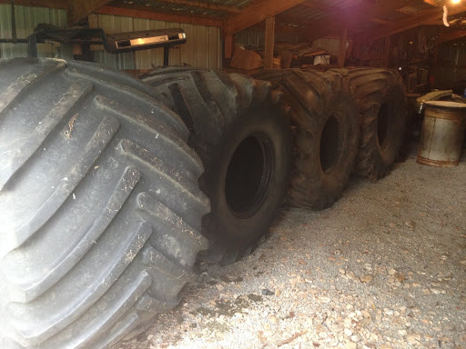

As mentioned, I now have all 4 tires. I still only have 3 wheels, but I have a 4th wheel located for $150.00. Hope to go get that sometime after Christmas.
Well, maybe this post is long enough to score me a Nobel prize in literature...... Leo Tolstoy would be proud.
 1
1